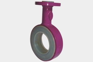
Design Specifications
- Flange : As per ANSI B16.5 / B 16.42
- Face to Face : As per ANSI B 16.5 #150
- Lining Thickness : 3 to 5 mm
- Other Flange Drillings like, DIN 2632 / 2633, BS 10 Table D, E or F are also available on request.
- Material
- Dimensional
- Test & Inspection
Housing Material Options
- Ductile Iron GGG40.3 / ASTM A395
- Cast Steel ASTM A216 Gr.WCB
- Steel Fabrication – ASTM A106 Gr.B SCH-40 Pipe.
Lining Material Options
- FEP – ASTM D 2116
- PFA – ASTM D 3307
- PVDF – ASTM D 3322
- PP – ASTM D 4101
- HDPE
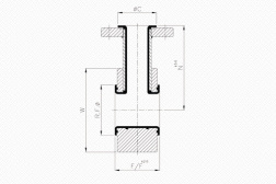
Dimensional Data
| ANSI #150 Flanged 25 NB BRANCH [ØC = 51 mm] | ||||
| SIZE | F/F (mm) | N(mm) | R.F.Ø (mm) | W (mm) |
| DN25-1” | 51 | 89 | 51 | 66 |
| DN40-1 1/2” | 51 | 102 | 73 | 85 |
| DN50-2” | 51 | 141 | 92 | 104 |
| DN80-3” | 51 | 160 | 127 | 136 |
| DN100-4” | 51 | 179 | 157 | 174 |
| DN150-6” | 51 | 205 | 216 | 222 |
| DN200-8” | 51 | 237 | 270 | 279 |
| DN250-10” | 51 | 264 | 323 | 339 |
| DN300-12” | 51 | 302 | 381 | 409 |
| ANSI #150 Flanged 40 NB BRANCH [ØC = 73 mm] | ||||
| SIZE | F/F (mm) | N(mm) | R.F.Ø(mm) | W mm) |
| DN40-1 1/2” | 76 | 102 | 73 | 85 |
| DN50-2” | 76 | 141 | 92 | 104 |
| DN80-3” | 76 | 160 | 127 | 136 |
| DN100-4” | 76 | 179 | 157 | 174 |
| DN150-6” | 76 | 205 | 216 | 222 |
| DN200-8” | 76 | 237 | 270 | 279 |
| DN250-10” | 76 | 264 | 323 | 339 |
| DN300-12” | 76 | 302 | 381 | 409 |
Test & Inspection Data
- Resins are confirming to the requirements of ASTM F1545-97 (2003)
- Hydraulic Test : 29 Kg/Cm2 After Lining
- Spark Test : 15 KV D.C After Lining
Technical Information subject to change without notice.


Connect with Us