

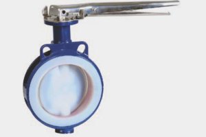

Standard Scope Of Supply
1.Wafer Type BodyASTM A216 Gr.WCB†
| NO. | Description | MOC |
|---|---|---|
| 2. | Body Liner | PFA / PTFE |
| 3. | Disc With Integral Shaft | SS 304 Encapsulated With PFA |
| 4. | Elastomer Backup | Silicon |
| 5. | Wedge Ring | PTFE |
| 6. | Thrust Washer | S.S. |
| 7. | Support Bush | TFM / SS PFA LINED / Coated |
| 8. | Guide Bush | S.S. PTFE Coated |
| 9. | Lever Assembly | CS |
Salient Features
- ‘Maintenance Free’ High Performance Design
- Bubble Tight Closer provides process efficiency
- Dynamic Live Loaded Seal Design give super safe operation.
- Intact Performance in severe conditions of corrosion, abrasion, and temperature fluctuation.
Technical Specifications
- Design Standard : BS EN 593:2004 (Formerly BS 5155)
- Drilling : ANSI B16.5 / DIN PN10/16
- Face to Face : API 609 / DIN 3202 K1 / BS 5155 / ISO 5752 / BS EN 558-1/2
- Lining Thickness : 3 to 5 mm
- Testing Standard : BS EN 12266-1&2 (2003)
- Material
- Dimensional
- Test & Inspection
- Optional Design
Body Material Options
- Cast Steel ASTM A216 Gr.WCB
- ASTM A351 Gr. CF8 / S.S.304
- ASTM A351 Gr. CF8M / S.S.316
Lining Material Options
- PTFE – ASTM D 4895
- PFA – ASTM D 3307
- FEP – ASTM D 2116
- ETFE – ASTM D 3159
- PVDF – ASTM D 3322
Dimensional Data
- * Smallest Pipe Ø of connecting pipe for Inline Mounting.
- $ ‘C’ Shows the minimum clearance required between Valve Disc & Pipe ID
- ♦ per Manufacturer’s Standard † As per BS EN 558-2,Table-5,Series-20
- § Torque measured at ΔP = 11 Bar at Room Temperature in Wet Condition (Test Media – water).
| Suitable to Mount Between ANSI #150 / PN10-16 Flanges | |||||||
| SIZE | F/F†(±2) (mm) | A (mm) | B (mm) | L (mm) | Min. PipeØ* (mm) | C$ (mm) | Torque§(N.m) |
| DN40-1 1/2” | 33 | 90 | 65 | 260 | 26 | 1.5 | 15 |
| DN50-2” | 43 | 100 | 67 | 260 | 29 | 1.5 | 30 |
| DN65-2 1/2” | 46 | 115 | 65 | 260 | 49 | 1.5 | 40 |
| DN80-3” | 46 | 120 | 80 | 260 | 68 | 1.5 | 40 |
| DN100-4” | 52 | 158 | 95 | 260 | 88 | 1.5 | 50 |
| DN150-6” | 58♦ | 190 | 120 | 325 | 145 | 1.5 | 100 |
| DN200-8” | 64♦ | 220 | 162 | G.Box | 196 | 3 | 180 |
| DN250-10” | 70♦ | 250 | 200 | G.Box | 245 | 3 | 250 |
| DN300-12” | 80♦ | 270 | 232 | G.Box | 293 | 3 | 350 |
| DN350-14” | 92 | 300 | 255 | G.Box | 332 | 3 | 500 |
| DN400-16” | 102 | 300 | 290 | G.Box | 378 | 3 | 600 |
| DN450-18” | 114 | 395 | 310 | G.Box | 430 | 3 | 1200 |
| DN500-20” | 127 | 420 | 342 | G.Box | 480 | 3 | 1500 |
| DN600-24” | 156♦ | 510 | 400 | G.Box | 572 | 6 | 2000 |
Test & Inspection Data
- Hydraulic Test : Body (Shell) – 20 Kg/Cm
- Hydraulic Test : Seat – 11 Kg/Cm
- Pneumatic Test : Seat – 6 Kg/Cm
- Spark Test :15 K.V. D.C
Optional Design & Components
- Gear Box / Actuator
- Unlined Disc – Astm A351 Gr.CF8 / CF3M
- Extended Stem Design
- Lug Type Design
Technical Information subject to change without notice.

Connect with Us